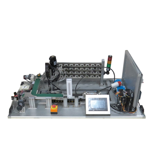
This training device is mainly composed of various types of industrial sensors, pneumatic control units, electrical switches, PLC programmable logic controllers, human-machine interfaces, etc. It consists of silo units, conveyor belt modules, RFID sensors, vacuum suction cup handling modules, A mechatronics equipment mechanical platform composed of two-axis manipulator handling modules, three-dimensional storage modules, touch screen units and other workstations. Through related experiments, you can be familiar with the operating characteristics of pneumatic system actuators. Based on the Siemens 1200 PLC motion control system, touch screen and PLC communication methods, etc., students can cultivate the corresponding knowledge and skills, suitable for higher vocational, college, secondary vocational schools and related majors in technical schools Teaching and skill training assessment
(1) The training platform adopts aluminum alloy base plate to build the training platform with a stable structure. Each actuator module is placed on the base plate, which is easy to use and not easy to damage. (2) The power distribution and PLC control unit of the training device adopts the switchboard mode, the power supply of the system is drawn through the safety plug, and the wiring of the training device is connected through the wiring, which is safe and reliable. (3) The organic integration of mechanical technology (including pneumatic technology), sensor technology, PLC control and communication network technology reflects the characteristics of the production process of modern manufacturing. The overall structure adopts open and disassembly type, which can easily replace the modules. The content of the modules is determined according to the principles of productive functions and integrated learning functions, so that the required modules can be easily selected during teaching or competition. (4) The I/O terminals of the master and slave PLC modules of the training and assessment device are connected to the command switches, photoelectric switches, sensors and indicating components through the terminal block.
The power input terminal is placed in the power distribution area on the training platform, led out through the plug, and the total power supply of the system is controlled by the leakage circuit breaker.
(1) The training platform is composed of an aluminum alloy substrate, which can be placed on a horizontal table for experiments, with a firm structure and beautiful appearance. (2) Accessories Block Cable
The power control part is shown in Figure 0, Figure 0 Power supply unit 1- Leakage circuit breaker 2- Switching power supply 3- PLC module 4- Control relay 5- Switch 6- sockets block 7- Extension module (1) Three-phase five-wire power input, controlled by a circuit breaker. (2) Equipped with 24V 3A switching power supply for training objects and loads.
1. Compressed air input unit The compressed air input unit interface of the training device is shown in Figure 1. The compressed air is supplied to all the pneumatic components of the device through the pressure reducing valve. The outlet end of the pressure reducing valve is controlled by a valve, which is convenient for device debugging. When the system is running, adjust the pressure value of the pressure reducing valve to 0.4MPa (pull up the pressure adjustment knob, turn the knob to adjust the pressure value to 0.4MPa, after the adjustment is completed, press the knob down to lock the knob and prevent it from rotating) . Figure 1 Compressed air input unit 1- Pressure adjustment knob 2- Air inlet 3- Switch valve 4- Pressure gauge 2. Silo unit The silo unit is used to place the cylindrical material block to be transported. When the system is running, the material block is pushed out to the conveyor belt by the pushing cylinder for transportation. The silo unit is shown in Figure 2. Figure 2 Feeding station unit 1-Round block silo 2-Pushing cylinder
3. Conveyor belt unit The conveyor belt unit is used to carry cylindrical material blocks. The conveyor belt is composed of two sections, which are respectively driven by a DC reduction motor 1 and a DC reduction motor 2. The conveyor belt unit is shown in Figure 3. Figure 3 Conveyor belt unit 1-DC geared motor 1 2-conveyor belt 1 3-conveyor belt 2 4-DC geared motor 2 4. Vacuum suction cup handling unit The vacuum suction cup handling unit is used to transport the cylindrical material block to the square pallet, and then the robot handling module transports the square pallet to the square pallet bin. This unit is mainly composed of vacuum suction cups, rotating cylinders, and square tray bins. The vacuum chuck handling unit is shown in Figure 4. Figure 4 Vacuum suction cup handling unit 1-square pallet silo 2-vacuum suction cup 3-rotating cylinder 5. Three-axis manipulator handling unit The handling manipulator unit is the core part of the whole system's actuator, which is composed of up and down movement modules, left and right movement modules, cylinder trays, position sensors, etc. The left and right movement modules and the up and down movement modules are respectively driven by servo motors as shown in Figure 5. Figure 5 Transport robot unit 1-Elevating servo motor 2-Indicating lamp 3-Move left and right servo motor 4-Limit sensor 5-Servo controller 6. Stereoscopic warehouse unit The three-dimensional warehouse unit is composed of warehouse positions and position switches. The three-dimensional warehouse is divided into four floors with a total of 32 warehouse positions. The material blocks are transported to the corresponding warehouse positions in order by the robot. The three-dimensional warehouse unit is shown in Figure 6. Figure 6 Three-dimensional warehouse unit 7. PLC and power distribution unit This training system uses Siemens 1200 series PLC, the CPU is 1214C transistor output, and two 1221-1BH32-0XB0 and one SM1223 DI 8X24 24VDC are added. The PLC and expansion module units are all connected to the execution object and sensors, and the CPU module and digital module are led to the terminal panel through internal wiring. PLC and power distribution control unit are shown in Figure 7. Figure 7 PLC and power distribution control unit 1- Leakage circuit breaker 2- Switching power supply 3- PLC module 4- Control relay 5- Switch 6- Terminal block 7- Extension module 8. Touch screen unit The touch screen unit is used to control the movement of the manipulator and display the warehouse materials. Display the current coordinates, display the material block code, and display the storage status of the warehouse. The bottom of the touch screen is equipped with start, stop and emergency stop buttons. The touch screen control button unit is shown in Figure 8. Figure 8 Touch screen unit