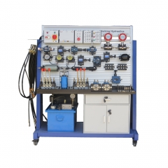
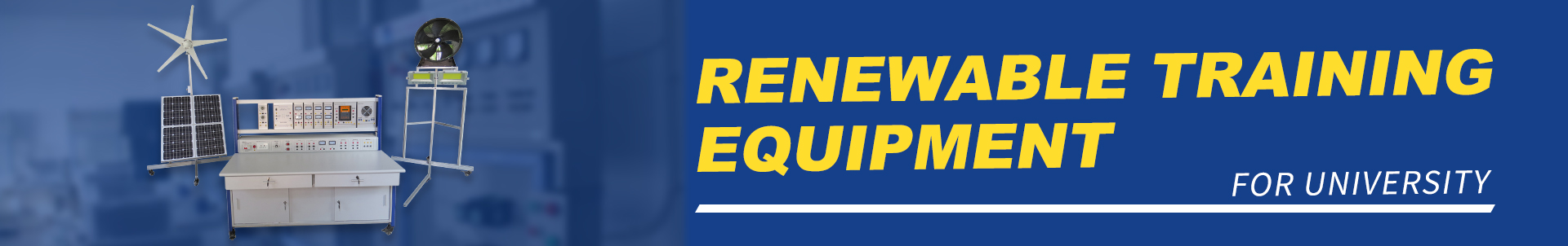
MR089M Basic Level: Mobile Hydraulics – Working Hydraulics Vocational Training Equipment Mechatronics Trainer
I. Product description 1.1 Overview This hydraulic training device adopts the open structure operation panel design according to the syllabus requirements of mechanical and electrical integration of colleges and universities for gas, electricity and hydraulic control, combined with the advantages of pneumatic relay control and hydraulic relay control experimental equipment. Various hydraulic components can be flexibly installed on the operating panel. All joints adopt open-close quick joints at both ends, which solves the problem of oil leakage in the hydraulic circuit, is convenient and durable, reduces losses and also helps maintain environmental sanitation. Arbitrary combination of various components to form a hydraulic system with certain functions, with strong practicality. 2 Features (1) The equipment is composed of a high-strength sheet metal frame, which is beautiful and durable. The bottom is equipped with universal wheels for easy movement; equipped with a cabinet for storing tools and devices, and the hydraulic station is integrated in the lower part of the equipment; various hydraulic valve blocks are fixed The substrate adopts special substrate profiles, and the groove interval of the panel is 25mm, which can easily plug various components on it; the upper part of the electronic control hanging box is placed, the whole is compact. (2) Equipped with industrial series hydraulic valves, the maximum working pressure can reach 35Mpa. Each hydraulic component is equipped with an oil circuit transition base plate, which can be conveniently and freely placed on the panel. The oil circuit lap connection adopts open-close quick-change joints, which is convenient for disassembly and connection, does not leak oil, reduces loss and also helps maintain environmental sanitation. II. Performance parameter (1) Input power: AC: 220V (2) Experimental table size: 1650 (length) × 700 (width) × 1800 (height) (3) Aluminum alloy panel size: 1200 (length) × 750 (width) (4) Groove interval: 25mm (5) Specifications: Cabinet: 1 (6) Desktop structure: 1 (7) Casters with split grooves: 4 (8) Safety limit speed range: 1000-1500 rpm (9) The noise at a distance of 1.5m from the hydraulic platform when the hydraulic pump is working is less than or equal to 58dB0 (10) Demonstration experiment requires only 4-6Mpa for fluid flow pressure (11) Fuel tank: Nominal volume 35L 3.1 Electric control unit The electrical control unit includes a master control switch hanging box, a DC power supply hanging box, an emergency stop hanging box, a relay hanging box, and a button hanging box. 3.2 Training platform The training platform is composed of aluminum profiles and aluminum alloy substrates, which can be moved and positioned flexibly. The actuator control box is installed on the base plate, which is beautiful and generous. 3.3 Power configuration Single-phase three-wire power input, protected by insurance, is equipped with a main power switch. In an emergency, turn off the main power switch to stop the execution object. 3.4 Hydraulic Components Picture, model and Chinese name of hydraulic components.
Balance valve DC6G-1-10B/50/2
Diaphragm accumulator:
3-way pressure regulator:DR6DP-50/75
pressure relief DBDH6P/100
flow control valve DV8/1
1 unit shuttle valve double nonreturn valve, delockable 4WE6J-6X /ED24V
6/3-way proportional units: hand lever valve
loading unit / cylinder
loading unit / cylinder
pressure compensator for open center load sensing:
hydraulic motor
anti-shock unit and anti-cavitation block:Direct-acting relief valve DBDH6P/100
4/3-way hand lever valve:4WMM6D50B/
Electronics pressure switch:Setting method:
Connect the red and black wires to the power cord, turn off the run button, press the SET button twice, AL (lower limit pressure) will appear, press the upper button to adjust the lower limit start value, Press SET again, AH (upper limit pressure) will appear, press the upper key to adjust the upper limit stop value, Press SET again, SAVE (data saving) appears, Press SET again to return to the measurement interface, Click to run, you can use it. For example: 0.5Mpa start 0.8mpa stop AL is set to 0.5mpa, AH is set to 0.8mpa, the contact between yellow and blue is normally open, and the pressure is within the setting range.
Flow sensor
Steering valve(orbitrol)
Tubing line for pressureless DR10/200Y
manifold plates
T-distributors、return header, 4-way, pressureless and nonreturn valve
Oil tube
Hydraulic power station
IV. Precautions 1. The incoming power supply of the experimental device should be correctly connected, and the grounding should be good and reliable. 2. When using, keep your hands dry and clean, and pay attention not to scratch the surface of the equipment with sharp objects. 3. During the experiment, after the wiring is correctly connected, the instructor should confirm that it is correct before energizing the experiment. It is strictly forbidden to touch the live parts with your hands or conductive objects, and you will be responsible for the electric shock in violation of regulations. 4. After using the experimental device, turn off the main power switch and unplug the power plug from the socket. 5. When the cylinder and conveyor belt are working, it is strictly forbidden to touch the cylinder push rod and the motor rotating shaft with your hands to avoid accidental injury. 6. When encountering an emergency, disconnect the system power supply or turn off the main power switch of the control box in time. V. Experiment content: Experiment 1. Reversing circuit of hand lever valve Experiment 2. The reversing circuit of the shuttle valve double nonreturn valve,delockable Experiment 3. Single-stage regulator circuit Experiment 4. Single-stage pressure reducing circuit Experiment 5. Secondary pressure reducing circuit Experiment 6. Unloading circuit using 4/3-way hand lever valve Experiment 7. Unloading circuit using 4/2-way lever valve Experiment 8. Balance circuit with sequence valve Experiment 9. Brake circuit with overflow valve Experiment 10 Secondary pressure circuit Experiment 11. Throttle speed regulating circuit of oil inlet Experiment 12 Throttle and speed control circuit Experiment 13. Throttle speed regulation circuit Experiment 14. Throttle valve parallel circuit Experiment 15. flow control valveseries circuit Experiment 16. Locking circuit using shuttle valve double nonreturn valve,Delockable Experiment 17. loading unit test loop